Light
Reflection of Light
Just like any other wave, light can be reflected off a plane surface. A basic mirror uses the principles of reflection to allow us to see various objects through it.
Basic Principles of Reflection
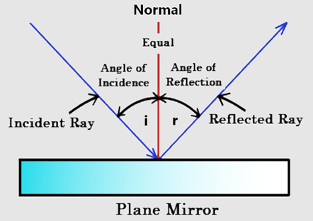
There are some key principles regarding the reflection of light rays:
- The incident ray, reflected ray, and the normal all lie in the same plane
- The incoming light ray is called the ‘incident ray’
- The reflected light ray is called the ‘reflected ray’
- The normal is the imaginary perpendicular line on the mirror surface
- The angles of the rays are measured in relation to the normal
- The angle of incidence is the angle between the incident ray and the normal
- The angle of reflection is the angle between the reflected ray and the normal
- The angle of incidence is always equal to the angle of reflection
Reflection through a plane mirror
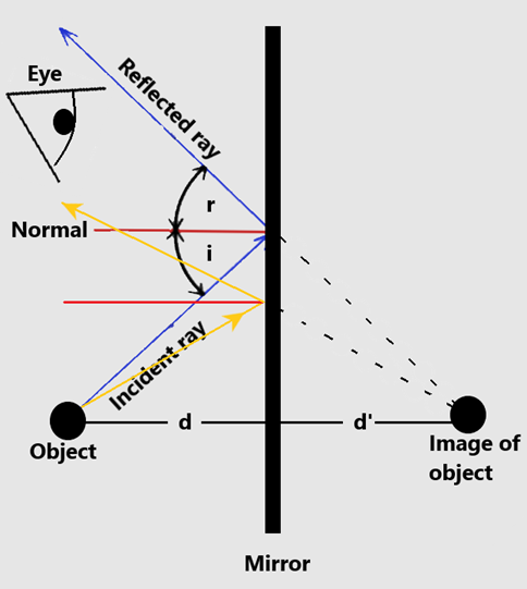
A mirror reflects light rays that come from various objects. These reflected rays enter our eyes and allow us to see these objects through the mirror.
We can construct a ray diagram to demonstrate how the image of an object is formed inside a mirror:
- Trace at least 2 incidents rays from an object
- Trace the corresponding reflected rays ensuring that you follow the law of reflection (r=i)
- Trace back the reflected rays, and the lines should converge at a single point behind the mirror
- That convergence point is where the image is located
- If everything went smoothly, the distance from the real object to the mirror should be the same as the distance from the mirror to the image (d = d’)
You need to be able to perform simple constructions, measurements, and calculations for reflections by a plane mirror.
The properties of an image inside a mirror are:
- Virtual image
- Real images are those where light actually converges, whereas virtual images are locations from where light ‘appears’ to have converged when traced backwards (like in our diagram above)
- Same size as object
- Same distance away from mirror as object
- Laterally inverted
Refraction of light
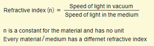
Refractive index – Light travels at different speeds depending on the refractive index of a medium. Every material/medium has a different refractive index, and this value is determined by how fast light travels within it.
- The higher the refractive index, the slower light travels
- The lower the refractive index, the faster light travels
Generally, denser materials have a higher refractive index than less dense materials. The equation for refractive index is as follows:
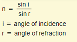
Two other very important equations are:
Continue reading, as we will discuss more in depth about the angle of incidence, angle of refraction, and the critical angle!
Refraction of light rays through mediums – Consider light traveling from medium A to medium B. Two scenarios are possible:
- Medium A has a lower refractive index than medium B
- Medium A has a higher refractive index than medium B
Air has a lower refractive index than glass. Consider light entering a glass block from the top and leaving through the bottom.
- As light enters the glass block, it goes from low to high index
- As light escapes the block, it goes from high to low index
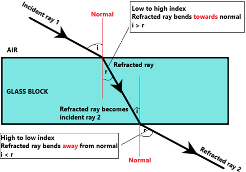
Here are some important notes about the diagram above:
- i = angle of incidence
- r = angle of refraction
- Light slows down as it enters a higher index material, therefore bends towards the normal
- Light speeds up as it enters a lower index material, therefore bends away from the normal
If light ever enters another medium at exactly 90° (along the normal) then light changes speed but does not change direction.
Critical angle and total internal reflection – Consider light rays going from a medium of higher to lower index. As discussed above, light rays will bend away from the normal.
As the angle of incidence increases, the angle of refraction also increases. However, there is a limit to this:
The angle of refraction cannot exceed 90°. After all, how could it? If light bent more than that then it would actually just reflect back into the medium.
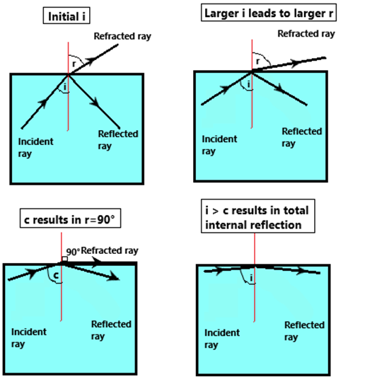
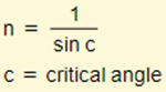
Therefore, the critical angle is the angle of incidence at which the angle of refraction is exactly 90°.
Recall that refractive index (n) = 1 / sin c
Total internal reflection is when the angle of incidence exceeds the critical angle and all the light gets reflected back into the medium instead of being refracted.
Total internal reflection used in optical fibres: The concept of total internal reflection is used in optical fibres. An optic fibre has a thin glass cylindrical core with a transparent material of a lower refractive index (cladding). The cladding has a lower refractive index than the core, meaning total internal reflection will occur for all rays that hit the boundary between the core and the cladding at an angle larger than the critical angle.
Thin Converging Lens
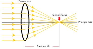
When parallel light rays from a distance source pass through a convex converging lens, they are focused at a single point called the principle focus.
The imaginary horizontal line which lies perpendicular to the lens is called the principle axis, and the distance from the lens centre to the principle focus is called the focal length.
If a beam of parallel light passes through a convex lens, this is the effect that you would get:
Drawing ray diagrams
You are expected to trace rays from an object through a convex lens in order to determine the position of the image.
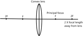
As we saw above, all convex lenses will have a certain focal point. The focal point and focal length are exactly the same on either side of the lens.
Start by drawing these components in order:
- Principle axis
- Convex lens
- Two focal lengths on either side of the lens
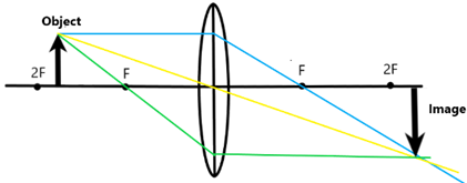
Consider an object being placed on the left-hand side of the diagram. There are three possible positions:
- Beyond 2F
- Between 2F and F
- Between F and the lens
The resulting image property of the object will be different depending on the object position.
Beyond 2F – From the top of the object, you draw three rays as shown in the diagram. The point at which these 3 lines meet is where the object is positioned.
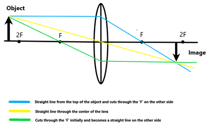
When the object is beyond 2F, the image is real, inverted, and diminished (smaller than the object).
Between 2F and F
When the object is between 2F and F, the image is real, inverted, and magnified (larger than the object).
Between F and the lens centre
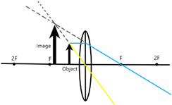
When the object is between F and the lens centre, the image is virtual, upright, and magnified.
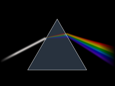
White light and dispersion
White light is a complex combination of all of the different wavelengths of the visible spectrum. Each of the wavelengths have a different colour i.e. green has a wavelength of approx. 500nm, red has a wavelength of approx. 700nm etc. Light of a single frequency is called monochromatic light, and combining all of these different individual wavelengths of monochromatic light result in ‘white light’. We can reverse this process by ‘splitting apart’ white light into its different components. This is called dispersion, and it can be easily done using a glass prism.