
Electromagnetic Effects
Electromagnetic induction
A conductor (such as a wire) moving across a magnetic field or a changing magnetic field linking with a conductor can induce an e.m.f in the conductor.
When a bar magnet is moved towards and away from a coil, it induces emf (and therefore current) within the coil. This is because magnetic field lines of the magnet get ‘cut’ from the coil.
The magnitude of e.m.f induced in the coil can be increased by:
- Moving the magnet faster
- Putting more turns in the coil
- Using a strong magnet
- Total area of the coil
Let’s look at this in a bit more detail. Consider this set-up below:
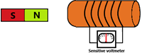
Bar magnet moving towards the coil – When the north pole of the bar magnetic is moved towards the coil, the needle on the voltmeter briefly flick to the right, before returning to the centre.
As the bar magnet moves into the coil, the coil cuts the magnetic field lines of the bar magnet. This induces an emf across the coil which is measured by the voltmeter.
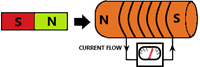
The emf across the coil can cause a current to flow in the coil if it is a complete circuit. The current that flows can cause the coil to act like a bar magnet.
When the north pole is moved towards the coil, the induced emf (or current) induces a north magnetic pole at the end of the coil (which repels the bar magnet’s north pole). Therefore, the emf that is induced will always oppose the change of the bar magnet i.e. attempts to push it away as it moves closer
Bar magnet moving away from the coil – When the north pole of the bar magnetic is moved away from the coil, the needle on the voltmeter will flick to the left.
This is because the coil cuts the field lines in the opposite direction, so the induced emf is also in the opposite direction.
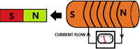
When the north pole is moved away from the coil, this induces a south pole at that end of the coil. The induced emf has therefore induced a magnetic pole which opposes change of the bar magnet i.e. attempts to pull it in while it is moving away
A.C Generator
You must be aware of the difference between A.C and D.C current
- A.C stands for alternating current, where the direction of the current changes periodically.
- D.C stands for direct current, which has unidirectional current.
An A.C generator is a set-up used to make A.C current. It uses the fundamentals of electromagnetic induction that we looked at before.
The set-up
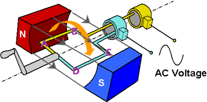
- Between two magnetic poles, a rectangular coil with sides (labelled A, B, C, and D) is placed.
- The rectangular coil is connected to two slip rings (coloured yellow & cyan)
- Side A+B of coil are connected to the yellow slip ring
- Side C+D of coil are connected to the cyan slip ring
- The slip rings are connected to an external circuit
- The coil is forced to rotate, and as it does so, generates alternating current in the external circuit
Each time one side of the coil (either AB or DC) end up in a vertical position, the induced current changes direction – hence alternating current. Why this happens will be discussed below.
How it works
- Magnetic field lines go from north pole to south pole
- As the coil rotates, it cuts the magnetic field lines and induces emf and current
- In the diagram above, as the coil rotates, side AB will cut the magnetic field upwards while side CD cuts the field downwards
- This will induce an emf and current within the coil, in a particular direction
- As the coil rotates further, side AB will eventually cut the magnetic field downwards while side CD cuts the field upwards
- Since the sides have now reversed, the direction of induced current will also become reversed too
At any given point, the Fleming’s right hand rule can be used to determine the direction of induced current. However, it is not expected for you to know this within the scope of IGCSE physics.
Interpreting the A.C voltage against time graph
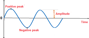
Consider a completely vertical coil with side AB being at the top and side CD being at the bottom.
When the coil is vertical, the emf induced is 0. As the coil rotates, the emf begins to rise. When AB and CD is completely horizontal, the induced emf is at its peak. Further rotation begins to reduce the emf until the coil is vertical again (this time CD is at the top and AB is at the bottom).
Further rotation begins to rise the emf but this time, in the opposite direction of the graph.
Transformer – A transformer increases or decreases the voltage of an alternating current.
The general contraction of a basic transformer is as follows:
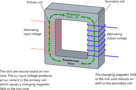
A step-down transformer produces an output voltage that is less than the input voltage – Secondary coil has less turns than the primary coil
A step-up transformer produces an output voltage that is greater than the input voltage – Secondary coil has more turns than the primary coil
Here are some important equations that you must learn:
Vs ÷ Vp = Ns ÷ Np
[Vs = Voltage across secondary coil, Vp = Voltage across primary coil, Ns = No. of turns in secondary coil, Np = No. of turns in primary coil]
At 100% Efficiency, Input Power = Output Power
P = IV so therefore, IpVp = IsVs
Step-up transformers are used to step up voltage coming from a power station onto the power lines that transmit electrical energy.
The power from the power station is constant and thus increasing the voltage decreases the current (P = VI). Voltage is therefore amplified by transformers to keep the current low.
Low current is beneficial because the larger the current, the more energy is lost through heat which reduces the efficiency of the transmission.
Magnetic Effect of a Current
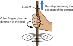
The magnetic field around a straight current carrying wire look like simple rings. The direction of the field can be determined by using the right hand grip rule.
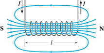
The magnetic field around a solenoid is much like that of a bar magnetic. The direction of the field lines depends on where the north and south poles are on the solenoid, which is dependent on the direction of current.
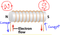
At any given point, the direction of a magnetic field line is the direction of force on the north pole of a magnet at that point.
Here are some visual examples of various magnetic field sources. The single wire, solenoid, and the bar magnet are the main ones to note.
Force on a Current Carrying Conductor
Recall that a wire carrying current has a magnetic field around it. The direction of current can be determined by using the right-hand grip rule.
If the wire is placed in another magnetic field, then the two fields with interact and there will be a force on the wire.
Consider a wire carrying current I, placed in between the north and south poles of a magnet.
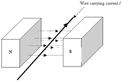
Can you figure out the direction of the force on the wire?
For any given situation concerning a magnetic field, current, and force (thrust), the Fleming’s left-hand rule can be used:
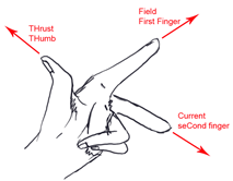
As long as you know the direction of two of these three variables, this rule will allow you to determine the direction of the unknown variable (in this case the force/thrust).
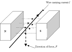
By applying this rule to the example above, you should now be able to see how the force is acting downwards on the wire.
D.C Motor
The basic set up of a D.C. motor is as follows:
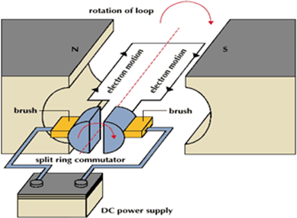
The poles of the magnet are curved to provide a circular magnetic field. This helps to keep the coil in a constant magnetic field.
Each side of the coil experiences a force due to the fact that it is carrying current within a magnetic field. This force causes the coil to rotation (clockwise in this case).
Remember, you can figure out the direction of force using Fleming’s left-hand rule. Try it with this example! Using the rule, you can see that the left-hand side of the coil has a force UPWARDS and the right-hand side has a force DOWNWARDS and therefore the rotation is clockwise.
The split-ring communicator turns with the coil and is always in contact with the brushes (which are fixed in place) to ensure that current continues to flow to the coil.
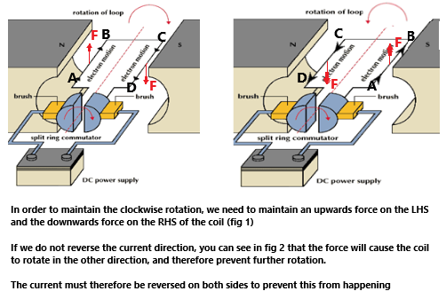
Each time the coil reaches a vertical position, the two sides of the communicator swap brushes. This reverses the flow of current to ensure that the force on each side also become reversed. This allows the coil to continue spinning. Otherwise it would just oscillate backwards and forwards.
If you are still confused, then take a look at this diagram below
The speed at which the coil spins can be increased by:
- Increasing the number of turns on the coil
- Increasing the current
- Increasing the strength of the magnetic field