
Digital Electronics
Digital Electronics
A digital system includes an input sensor and a processor circuit, which controls the voltage to an output device.
The processor circuit consists of a series of logic gates. Logic gates respond to small voltages which are either on or off. They do not respond to analogue signals.
- An analogue signal (V) varies continuously in amplitude
- A digital signal (V) has only two states: High or low (or on and off, or 1 and 0)
Logic Gates
Logic gates transform a digital input voltage into an output, which depends on the type of logic gate.
The input voltages are given as 1 or 0 (on or off) and the input/output of these logic gates can be represented on a truth table.
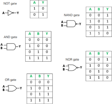
- A NOT gate gives an output that is opposite of the input
- An AND gate only gives an output if the input A and B are both 1
- An OR gate gives an output if input A or input B is 1
Logic gates can be combined to perform different functions in various electric circuits.
read more about logic gates here:
Digital and Analogue ammeters:
Digital (electronic read out), Analogue (needle and scale)
Analogue ammeters:
Subject to parallax and zero errors
Digital ammeters
Measure very small currents
More accurate than analogue displays
Easy to use
But displays my flicker back and forth, so judgement needed for which value to use
Check for zero error