
Processor Fundamentals
The Von Neumann model of a computer system
The model has the following basic features:
• There is a processor, a central processing unit.
• The processor has direct access to memory.
• The memory contains a ‘stored program’ (which can be replaced by another at any time) and the data required by the program. • The stored program consists of individual instructions.
• The processor executes instructions sequentially.
Central processing unit (CPU) architecture
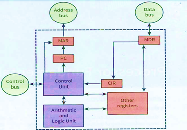
Components of the CPU
The two major components of the CPU are the arithmetic and logic unit (ALU) (or Arithmetic Logic Unit) and the control unit. As its name implies, the ALU is responsible for any arithmetic or logic processing that might be needed when a program is running. The functions of the control unit are more diverse. One aspect is controlling the flow of data throughout the processor and, indeed, throughout the whole computer system. Another is ensuring that program instructions are handled correctly. A vital part of the control unit is a clock which is used by the unit to synchronize processes.
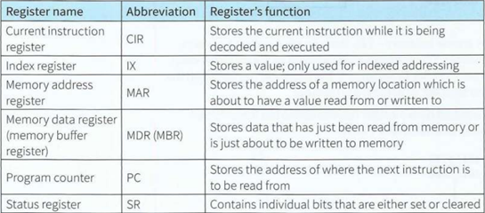
Registers
The other components of the CPU are the registers. These are storage components that, because of their proximity to the ALU, allowing very short access times. Each register has limited storage capacity, typically 16, 32 or 64 bits. A register is either general purpose or special purpose. If there is only one general-purpose register it is referred to as the accumulator.
Accumulator: a general-purpose register that stores a value before and after the execution of an instruction by the ALU
Registers in a simple CPU
The system Bus
The system bus allows data flow between the CPU, the memory, and input or output (I/0) devices
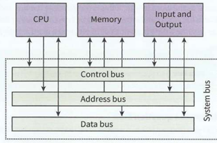
The address bus
Address bus: a component that carries an address to the memory controller to identify a location in memory that is to be read from or written to. The sole function of the address bus is to carry an address. This address is loaded onto the bus from the MAR as and when directed by the control unit The address specifies a location in memory that is due to receive data or from which data is to be read. The address bus is a ‘one-way street’.
The data bus
Data bus: a component that carries data to and from the processor. The function of the data bus is to carry data. This might be an instruction, an address, or a value.
The control bus
The control bus is another bidirectional bus that transmits a signal from the control unit to any other system component or transmits a signal to the control unit. There is no need for extended width so the control bus typically has just eight wires. A major use of the control bus is to carry timing signals.
USB
Universal Serial Bus is an industry-standard that establishes specifications for cables and connectors and protocols for connection, communication and power supply between computers, peripherals, and other computers
Fetch execute cycle
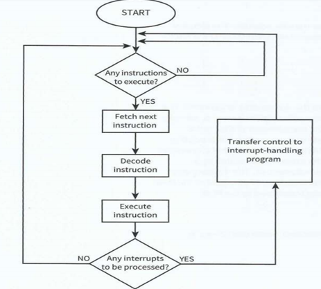
1 This address in the program counter is transferred within the CPU to the MAR.
2 During the next clock cycle two things happen simultaneously:
- the instruction held in the address pointed to by the MAR is fetched into the MDR
- the address stored in the program counter is incremented.
3 The instruction stored in the MDR is transferred within the CPU to the CI R. For our simple system the program counter will be incremented by 1. However, it should be noted that the instruction just loaded might be a jump instruction. In this case, the program counter contents will have to be updated in accordance with the jump condition. This can only happen after the instruction has been decoded.
In the decode stage, the instruction stored in the CIR is received as input by the circuitry within the control unit. Depending on the type of instruction, the control unit will send signals to the appropriate components so that the execute stage ca n begin. At this stage, the ALU will be activated if the instruction requires arithmetic or logic processing.
Register transfer notation
MAR <- [PC]
PC <- [PC] + 1; MDR <- [[MAR)]
CIR <- [MDR)
Interrupt handling
There are many different reasons for an interrupt to be generated. Some examples are:
• a fatal error in a program
• a hardware fault
• a need for I/0 processing to begin
• user interaction
• a timer signal.